
This lesson explores the essential hydraulic systems in Category T agricultural vehicles, crucial for operating various implements safely. You'll learn how fluid pressure works, the function of control levers, and critical safety features like emergency shut-offs. Understanding these systems is vital for both your Polish driving theory exam and safe, efficient real-world tractor operation.

Lesson content overview
Operating agricultural vehicles, particularly in Category T, requires a deep understanding of their powerful hydraulic systems. These systems are the muscle of a tractor, enabling tasks such as lifting heavy implements, operating loaders, steering, and driving various attachments. This lesson provides a comprehensive overview of hydraulic architecture, control mechanisms, essential safety features, and the critical maintenance practices required for safe and compliant operation on both private land and public roads in Poland.
Hydraulic systems are integral to modern agricultural machinery, converting mechanical power from the engine into fluid power to perform a wide array of demanding tasks. For Category T vehicle operators, a thorough grasp of how these systems function and how to safely manage them is paramount, not only for efficiency but also for preventing accidents and ensuring legal compliance under Polish traffic and machinery regulations.
At the heart of every hydraulic system is Pascal's Principle, which states that pressure applied to a confined fluid is transmitted equally in all directions throughout the fluid. This fundamental physical law allows a relatively small engine-driven pump to generate immense forces capable of lifting multi-tonne loads or exerting significant pressure for tasks like baling or plowing. This principle explains how a small push on a lever in the cabin can result in powerful movement of a large implement. Understanding this power is crucial for appreciating the safety measures built into the system.
An agricultural hydraulic system is typically a closed-loop fluid circuit, meaning the hydraulic fluid circulates within a sealed environment. This circuit comprises several interconnected components that work in harmony:
Each component plays a vital role in ensuring that power is efficiently transmitted and precisely controlled, allowing operators to manipulate heavy machinery with relative ease.
For Category T drivers, mastering hydraulic controls and understanding safety features is not merely about operational efficiency; it is a fundamental aspect of road safety and legal responsibility. A failure in the hydraulic system can lead to immediate and severe consequences, including loss of control over implements, damage to expensive equipment, or serious injury to the operator or bystanders. Polish law mandates that agricultural machinery must be maintained in a technically sound condition, with all safety devices fully functional, and operators must be properly trained in their safe use.
A robust understanding of each component in a hydraulic system is essential for effective operation and maintenance. Knowing the function and potential issues of these parts enables a proactive approach to safety.
Hydraulic fluid is a specially formulated oil that serves multiple critical functions: it transmits power, lubricates internal components, prevents corrosion, and helps dissipate heat. Unlike conventional motor oil, hydraulic fluid is designed to maintain a consistent viscosity (resistance to flow) across a wide range of operating temperatures, typically from -20 °C to +80 °C.
Choosing the correct fluid is crucial. Most agricultural systems use mineral-based hydraulic oils, specified by standards such as EN ISO 6743-2 (hydraulic fluid classification). Using incorrect fluids, such as standard engine oil or, worse, water-based fluids, can lead to severe damage, including corrosion, seal degradation, and pump failure.
The hydraulic pump is a mechanical device that converts mechanical energy from the tractor's engine or PTO (Power Take-Off) into hydraulic energy—creating pressure and flow. This pressurized fluid is then directed throughout the system to perform work.
Common types of hydraulic pumps include:
The pump's output, measured in litres per minute (L/min), must be sufficient to meet the maximum flow demand of all connected hydraulic actuators. Regular inspection for wear and leaks is mandated annually under Polish Vehicle Inspection guidelines (Rozporządzenie Ministra Infrastruktury) to ensure continued reliability and safety.
The reservoir, or hydraulic tank, is a critical component that stores the hydraulic fluid. Beyond simple storage, it provides space for the fluid to:
Essential features of a reservoir include a breather vent (to allow air in and out as the fluid level changes, preventing vacuum or over-pressurization), a sight glass or level indicator (to monitor fluid volume), and often internal baffling to aid cooling and de-aeration. Maintaining the fluid level between the minimum and maximum markers is crucial. A low fluid level can lead to pump cavitation, where air is drawn into the pump, causing noise, reduced performance, and accelerated wear. Reservoirs must be accessible for inspection and clearly labeled according to EU directive 2006/42/EC.
Hoses (flexible) and tubes (rigid) are the conduits that transport pressurized hydraulic fluid between all system components. They are connected by various fittings designed to withstand high pressures and prevent leaks.
In Poland, hydraulic hoses must comply with standards such as PN-EN 581-2, which often includes requirements for visible marking of the pressure rating.
Safety is paramount when operating powerful hydraulic systems. Various features and operator practices are designed to prevent accidental movements, protect components from damage, and allow for immediate intervention in emergencies.
The directional valve, also known as a control valve, is responsible for routing pressurized fluid to and from hydraulic actuators. Typically, a 4-way, 3-position valve is used for controlling a double-acting cylinder (which can both extend and retract).
Common positions for these valves include:
Modern systems may feature manual lever control, or power-assist controls (pneumatic or electric) to reduce operator effort. The ability of the valve to return to a center (neutral) position, often via spring-centering, is a critical safety feature preventing unintended motion when the control lever is released. Polish regulations require clear symbols and operable position indicators for these valves.
Control levers are the physical interface in the operator’s cabin that allow the driver to command specific hydraulic functions, such as lifting/lowering a three-point hitch, tilting a loader bucket, or operating an auxiliary implement.
Key safety design features include:
Under Polish legislation (Rozporządzenie o warunkach technicznych pojazdów), these levers must be easily reachable, clearly labeled, and designed to return to their neutral position when released by the operator. Failure to return levers to neutral when stopping or dismounting can lead to uncontrolled implement movement, a common cause of accidents.
The pressure relief valve is a crucial safety device designed to protect the hydraulic system from over-pressurization. It automatically opens and redirects excess fluid back to the reservoir when the system pressure exceeds a pre-set limit.
Pressure relief valves must be tested at least annually during vehicle inspection, and warning labels are required. Setting the relief valve too high effectively nullifies its protective effect, posing a significant risk.
A load-sensing system is an advanced feedback mechanism used with variable displacement pumps. It continuously monitors the actual hydraulic load (the demand for fluid flow and pressure) and modulates the pump's output accordingly.
While load-sensing systems enhance safety and efficiency, they do not eliminate the need for a pressure relief valve, which acts as the ultimate safeguard against excessive pressure. Load-sensing systems must be calibrated during periodic inspections to ensure optimal performance.
An emergency shut-off (E-Stop) mechanism is a dedicated control (often a prominently placed button or lever) designed to instantly cut hydraulic power to all actuators in an emergency. Some systems may also incorporate a dead-man switch, which automatically cuts power if the operator releases control or moves from their normal operating position.
Under Polish safety standards for agricultural machinery, E-Stop mechanisms must be functional and inspected quarterly. It is important to note that an E-Stop typically only cuts hydraulic flow, not engine power, allowing the engine to be safely shut down separately if needed.
Safety interlocks are mechanical or electronic links that prevent hydraulic actuation unless certain conditions are met. These are crucial for preventing dangerous motions or accidental engagement of implements.
Examples of common safety interlocks include:
Operators must never attempt to bypass or disable safety interlocks, as they are a critical layer of protection against unintentional movement and associated hazards. Always verify that interlocks are functioning correctly before beginning operations.
Regular maintenance and adherence to specific regulations are non-negotiable for the safe operation of hydraulic systems in agricultural vehicles, especially those used on public roads in Poland. Neglecting these duties can lead to system failure, accidents, and legal penalties.
Leak detection involves systematically checking the hydraulic system for any signs of fluid loss. Even minor drips can indicate a developing problem that could lead to significant fluid loss, reduced pressure, overheating, and environmental contamination.
Techniques for leak detection:
Fluid contamination is a leading cause of hydraulic system wear and failure. Contaminants can be external (dust, dirt entering through breather vents or during fluid top-ups) or internal (wear particles from pumps, valves, or cylinders).
Management of contamination:
Regular leak checks are required for road-legal agricultural vehicles under Polish Vehicle Inspection Ordinances. Ignoring leaks is not only dangerous but also illegal.
A structured approach to hydraulic system upkeep through a maintenance checklist is crucial for ensuring reliability and compliance.
Daily Checks (Before Operation):
Monthly Checks (or Every 50-100 Operating Hours):
Annual Comprehensive Service (by Qualified Service Center):
Article 39 of the Polish Road Traffic Act (Prawo o ruchu drogowym) mandates that all vehicles, including agricultural machinery, must be kept in a road-worthy condition, which explicitly includes functional and safe hydraulic systems. Proactive maintenance is thus a legal obligation.
Compliance with Polish and European regulations is mandatory for all Category T vehicle operators. These rules ensure that hydraulic systems are safe, environmentally friendly, and perform reliably.
| Rule | Applicability | Legal Status | Rationale | Example (Correct) | Example (Incorrect) |
|---|---|---|---|---|---|
| Hydraulic system must be inspected at least once every 12 months. | All Category T vehicles used on public roads | Mandatory (Polish Vehicle Inspection Ordinance) | Ensures road safety and system reliability, preventing failures that could cause accidents. | A farmer schedules an annual hydraulic system service and ensures the maintenance log is signed by a certified inspector. | A farmer skips the annual inspection to save time and costs, risking a traffic fine and unsafe operation. |
| Emergency shut-off must be operable without tools and easily accessible. | Any vehicle with hydraulic actuators | Mandatory (Rozporządzenie o warunkach technicznych pojazdów) | Allows for immediate cessation of dangerous hydraulic movements in an emergency, protecting operators and equipment. | The driver can instantly press a red E-Stop button on the dashboard, stopping all hydraulic flow. | The E-Stop is located behind a bolted panel, requiring tools to access it, making it ineffective in an emergency. |
| Pressure relief valve must be set not higher than 10-15% above normal operating pressure. | All hydraulic circuits | Mandatory (Manufacturer specifications, generally aligned with safety standards) | Prevents over-pressurization that can lead to catastrophic failure of hoses, seals, or other components. | A relief valve for a system operating at 210 bar is correctly set to open at 230 bar. | A mechanic sets the relief valve to 300 bar, well above the system's design limits, risking hose rupture under load. |
| Hydraulic fluid must meet EN ISO 6743-2 specifications. | All hydraulic equipment | Mandatory | Guarantees fluid performance, compatibility with system components, and safety across operating conditions. | A farm consistently uses ISO VG 46 hydraulic oil from a reputable supplier, ensuring it meets required specifications. | An operator uses cheap, non-specified engine oil in the hydraulic system, leading to premature pump wear and seal damage. |
| Control levers must return to neutral when released. | Manual control levers in the cabin | Mandatory (Polish Safety Standards for Agricultural Machines) | Prevents unintended movement of implements and ensures the system defaults to a safe, static state when not actively commanded. | The lever for the front loader automatically springs back to its central neutral position when the operator removes their hand. | The loader lever stays in the 'raise' position after use, causing the boom to slowly drift upwards without active control. |
| All hydraulic hoses must be visibly marked with pressure rating. | All vehicles with hydraulic hoses | Mandatory (PN-EN 581-2) | Allows operators and maintenance personnel to verify that the hose is suitable for the system's maximum operating pressure. | A new hose for the trailer brake system is clearly labeled "250 bar," matching the system's design pressure. | An old, unmarked hose is installed, making it impossible to confirm if it meets the required pressure rating, posing a burst risk. |
| Leakages must be repaired before the vehicle is permitted on public roads. | Any detectable leak | Mandatory (Polish Road Traffic Act – Prawo o ruchu drogowym) | Prevents environmental contamination (oil spills) and ensures that the hydraulic system maintains sufficient pressure for safe control of implements. | After discovering a minor leak at a fitting, the operator tightens it and cleans up the spill before taking the tractor on the road. | An operator ignores a dripping hose, leading to a visible oil trail on the road and potential legal action if stopped by authorities. |
The safe and efficient use of hydraulic systems in Category T vehicles often depends on adapting operations to various contextual factors.
Understanding the direct consequences of actions or failures within a hydraulic system is critical for preventing accidents:
Applying theoretical knowledge to practical situations is crucial for safe operation. Here are some scenarios illustrating correct and incorrect behavior regarding hydraulic controls.
Hydraulic systems are the backbone of modern agricultural operations. For Category T license holders in Poland, a profound understanding of their function, control, and safety mechanisms is not just a best practice—it is a legal and ethical imperative. From understanding Pascal's principle to meticulously performing daily maintenance checks and respecting regulatory requirements, every aspect contributes to a safe working environment and extended equipment lifespan.
The ability to operate these powerful systems responsibly, respond effectively to emergencies, and perform routine maintenance checks ensures both personal safety and compliance with Polish traffic law (Prawo o ruchu drogowym). By adhering to the principles outlined in this lesson, operators can minimize risks, maximize efficiency, and contribute to safer agricultural practices.
This lesson builds upon foundational knowledge from earlier sections of the Polish Driving License Theory – Category T course. The understanding gained here will be crucial for subsequent topics that involve practical application and advanced safety considerations.
This lesson covers the hydraulic systems powering Category T agricultural vehicles in Poland, explaining how Pascal's Principle enables fluid pressure to drive cylinders for lifting and operating heavy implements. Key components include the hydraulic fluid (which must meet EN ISO 6743-2 and maintain viscosity from -20°C to +80°C), the pump that converts mechanical energy to hydraulic power, directional valves that route fluid to actuators, and the critical pressure relief valve set 10-15% above normal operating pressure. Essential safety features include emergency shut-off mechanisms (requiring quarterly inspection), safety interlocks preventing accidental activation, and control levers designed to return to neutral when released. Legal requirements mandate annual inspection, visible pressure ratings on hoses (PN-EN 581-2), and prohibition of road use with any hydraulic leaks.
A short set of high-value points that capture the most important learning from this lesson.
Pascal's Principle allows a small engine-driven pump to generate immense forces capable of lifting multi-tonne loads through equal pressure transmission in a confined fluid
Hydraulic systems are closed-loop circuits comprising a reservoir, pump, control valves, actuators (cylinders/motors), hoses, filters, and coolers that work together to transmit power
Pressure relief valves must be set to open at 10-15% above normal operating pressure to prevent catastrophic over-pressurization of the system
Emergency shut-off (E-Stop) mechanisms must cut hydraulic power instantly, stopping all actuator movement within 0.5 seconds in hazardous situations
Polish law mandates annual hydraulic system inspection, fluid must meet EN ISO 6743-2 specifications, and all leaks must be repaired before the vehicle can be used on public roads
Explore all units and lessons included in this driving theory course.
Hydraulic fluid viscosity must remain consistent across -20°C to +80°C operating temperatures; never use non-specified oils as they cause seal degradation and pump failure
Control levers must spring-return to neutral when released; failure to do so causes unintended implement movement, a common accident cause
Hydraulic hoses must be visibly marked with pressure rating (typically 250 bar for agricultural applications) and replaced if wear exceeds 30% of wall thickness
The E-Stop typically cuts hydraulic flow only, not engine power, allowing the engine to be shut down separately if needed
Load-sensing systems improve efficiency but do not replace the pressure relief valve as the ultimate over-pressurization safeguard
Using incorrect hydraulic fluid (such as standard engine oil) instead of manufacturer-specified oil, leading to corrosion, seal degradation, and pump failure
Dismissing minor leaks as insignificant during inspection, which can escalate to significant fluid loss, pump cavitation damage, and environmental contamination
Bypassing or disabling safety interlocks (such as those requiring seatbelt fastening or PTO neutral engagement) to save time, eliminating critical accident prevention layers
Leaving control levers partially engaged after operation, causing implements to drift or continue moving unexpectedly, especially dangerous on slopes
Setting pressure relief valves too high (well above the 10-15% threshold) during adjustment, removing protection against over-pressurization and hose rupture
Lesson content overview
A short set of high-value points that capture the most important learning from this lesson.
Pascal's Principle allows a small engine-driven pump to generate immense forces capable of lifting multi-tonne loads through equal pressure transmission in a confined fluid
Hydraulic systems are closed-loop circuits comprising a reservoir, pump, control valves, actuators (cylinders/motors), hoses, filters, and coolers that work together to transmit power
Pressure relief valves must be set to open at 10-15% above normal operating pressure to prevent catastrophic over-pressurization of the system
Emergency shut-off (E-Stop) mechanisms must cut hydraulic power instantly, stopping all actuator movement within 0.5 seconds in hazardous situations
Polish law mandates annual hydraulic system inspection, fluid must meet EN ISO 6743-2 specifications, and all leaks must be repaired before the vehicle can be used on public roads
Explore all units and lessons included in this driving theory course.
Hydraulic fluid viscosity must remain consistent across -20°C to +80°C operating temperatures; never use non-specified oils as they cause seal degradation and pump failure
Control levers must spring-return to neutral when released; failure to do so causes unintended implement movement, a common accident cause
Hydraulic hoses must be visibly marked with pressure rating (typically 250 bar for agricultural applications) and replaced if wear exceeds 30% of wall thickness
The E-Stop typically cuts hydraulic flow only, not engine power, allowing the engine to be shut down separately if needed
Load-sensing systems improve efficiency but do not replace the pressure relief valve as the ultimate over-pressurization safeguard
Using incorrect hydraulic fluid (such as standard engine oil) instead of manufacturer-specified oil, leading to corrosion, seal degradation, and pump failure
Dismissing minor leaks as insignificant during inspection, which can escalate to significant fluid loss, pump cavitation damage, and environmental contamination
Bypassing or disabling safety interlocks (such as those requiring seatbelt fastening or PTO neutral engagement) to save time, eliminating critical accident prevention layers
Leaving control levers partially engaged after operation, causing implements to drift or continue moving unexpectedly, especially dangerous on slopes
Setting pressure relief valves too high (well above the 10-15% threshold) during adjustment, removing protection against over-pressurization and hose rupture
Explore search topics learners often look for when studying Hydraulic Controls and Safety Features. These topics reflect common questions about road rules, driving situations, safety guidance, and lesson level theory preparation for learners in Poland.
Browse additional driving theory lessons that cover connected traffic rules, road signs, and common driving situations related to this topic. Improve your understanding of how different rules interact across everyday traffic scenarios.
Understand essential maintenance procedures for tractor hydraulic systems, including leak detection, fluid management, and regular checks. Learn about Polish regulations governing hydraulic safety and compliance for Category T vehicles.

This lesson focuses on the maintenance of agricultural implements and attachments powered via the tractor’s PTO and hydraulic systems. It covers routine inspection of hydraulic lines, lubrication of moving parts, and verification of safety features before each use. Additionally, the lesson stresses the importance of keeping detailed maintenance logs and certification documents to satisfy legal standards.
This lesson focuses on the braking systems found on Category T vehicles, covering both service brakes for motion control and parking brakes for stability. It examines how braking performance varies with load and terrain and outlines safe stopping distances. The lesson also explains the operation of the power take-off (PTO), describing how power is transferred to implements and the safety precautions required during use.

This lesson outlines the emergency procedures a tractor driver must follow in case of a breakdown, trailer detachment, or accident. It covers immediate actions such as pulling over safely, deploying warning triangles, and using hazard lights to alert other road users. The lesson details the steps for reporting the incident, providing first aid, and securing the scene to prevent further hazards.

This lesson provides a systematic approach to pre-use inspections, covering essential components that must be checked before operating a tractor. Learners will learn how to assess tire pressure, test brakes, verify the operation of all lights and beacons, and examine hitch conditions. Performing these checks ensures vehicle roadworthiness and reduces the risk of mechanical failure during operation.

This lesson provides comprehensive guidelines for safely transporting agricultural equipment, focusing on proper load securing techniques and weight distribution calculations. It discusses route planning that accounts for road conditions, bridge weight capacities, and seasonal obstacles like mud or snow. The lesson also emphasizes the use of protective equipment and regular compliance verification for safe operations.

This lesson outlines the legal responsibilities of tractor drivers as stipulated by Polish traffic law, emphasizing the duty to comply with all rules of the road. It discusses the liability framework for accidents involving agricultural vehicles, including the need for appropriate insurance and potential penalties. The lesson also explains the importance of maintaining accurate documentation, such as registration papers and a driver’s licence.
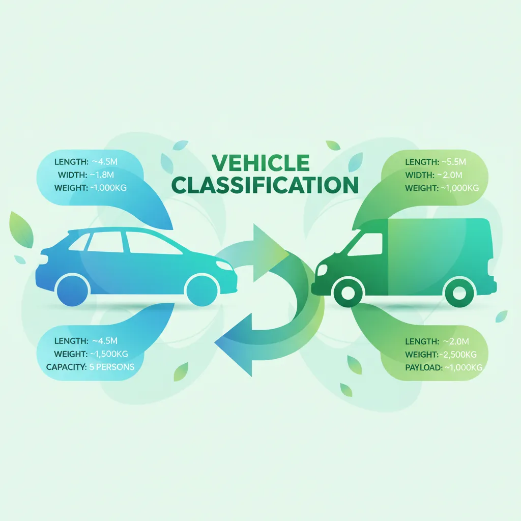
This lesson focuses on the precise classification of agricultural vehicles as defined by Polish law, differentiating between tractors, forestry machines, and trailers. It examines the legal parameters such as maximum permissible weight, width, height, and length that affect roadworthiness certifications. The lesson clarifies terminology used in official documents, ensuring learners can correctly identify the vehicles they are permitted to operate.

This lesson covers the fundamental procedures for starting and stopping a tractor, with emphasis on selecting the appropriate gear and clutch engagement for smooth motion. It explains how to manage traction on soft fields, loose gravel, and wet paved roads, and how to calculate safe stopping distances. The content also discusses hill starts and the prevention of wheel slip during acceleration and deceleration.

This lesson provides a step-by-step guide to safely coupling and uncoupling trailers, highlighting the correct use of hitches, drawbars, and safety chains. It emphasizes pre-couple inspections, alignment checks, and the necessity of confirming secure connections before movement. Learners will also study procedures for safely uncoupling, including establishing a safe zone and verifying trailer stability.
Find clear answers to common questions learners have about Hydraulic Controls and Safety Features. Learn how the lesson is structured, which driving theory objectives it supports, and how it fits into the overall learning path of units and curriculum progression in Poland. These explanations help you understand key concepts, lesson flow, and exam focused study goals.
The main components typically include the hydraulic pump, fluid reservoir, control valves, hydraulic cylinders (or motors), and a network of hoses and lines. These elements work together to generate, transmit, and control fluid power to operate various implements and attachments on a Category T tractor.
Safety valves, also known as relief valves, are crucial for preventing overpressure within the hydraulic system. If pressure builds too high, these valves automatically release excess fluid, protecting components from damage and preventing potentially dangerous failures, especially when operating heavy implements with a Category T vehicle.
Before starting, check the hydraulic fluid level in the reservoir and inspect all hoses, connections, and cylinders for any signs of leaks or damage. Ensure that all hydraulic control levers move freely and return to their neutral position. Listen for unusual noises during the initial system operation.
If a hydraulic hose bursts, immediately engage the emergency shut-off mechanism if available, or shut down the engine to stop the hydraulic pump. Secure any raised implements to prevent them from falling, prevent fluid contamination, and do not attempt to repair the hose yourself unless properly trained and equipped. Seek professional assistance.
While the PTO system directly transmits mechanical power from the tractor's engine to implements, many modern implements driven by the PTO also rely on the tractor's hydraulic system for their lifting, angling, or other operational functions. The hydraulic system provides the force and control for positioning these PTO-driven attachments on Category T vehicles.
Build custom practice sessions tailored precisely to your needs. Focus on areas requiring improvement, review specific Polish road signs, or master complex traffic rules to ensure full preparation for your official driving license exam.